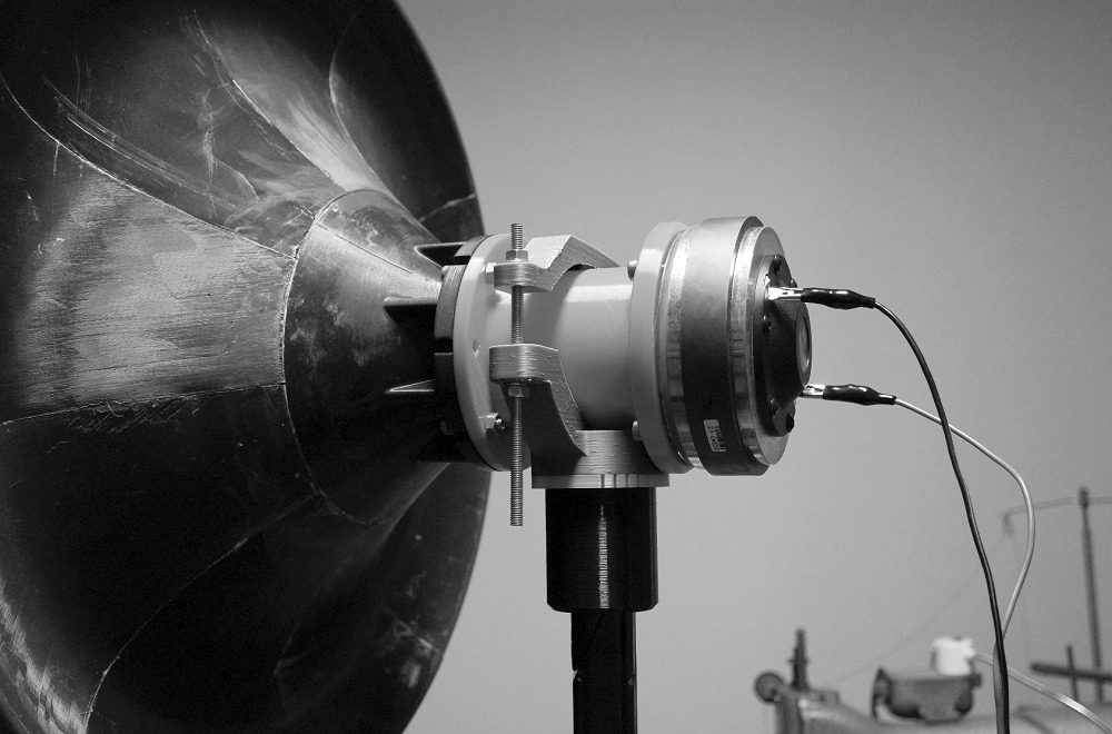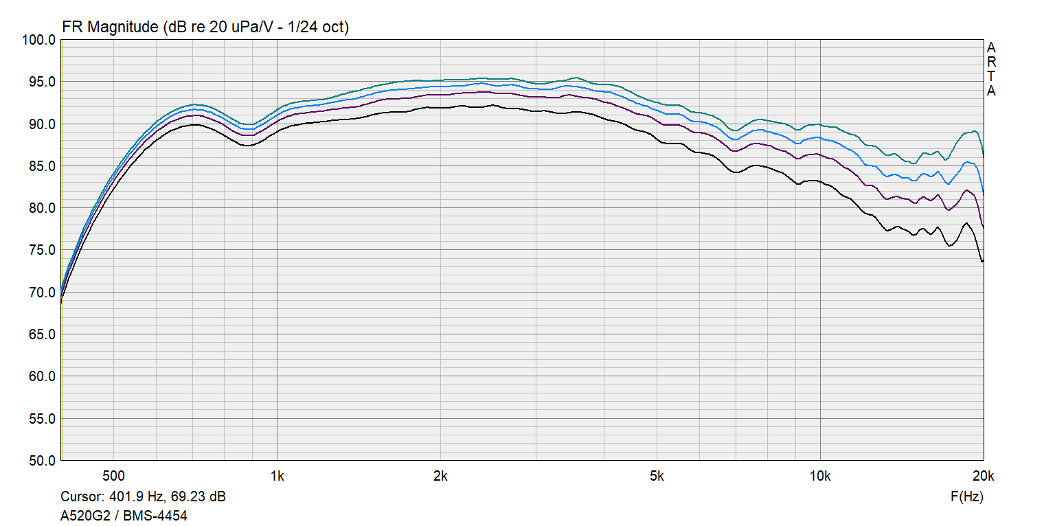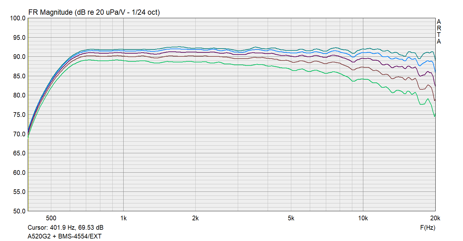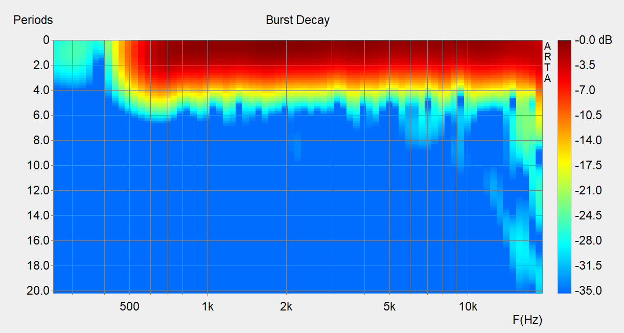

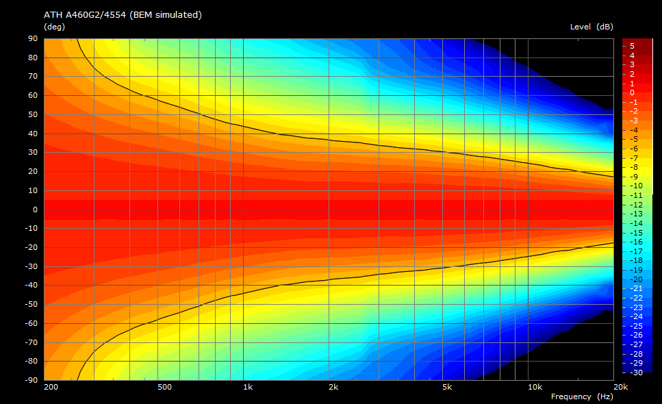
As the eariler experiment with a simple long conical adapter suggested[1], it is possible to extend the bandwidth of a compression driver in a waveguide to lower frequencies by inserting another "1P" degree of freedom in the initial part of the device. The presented Gen2 adapter is such an implementation, aiming for using the best-suited devices and design procedures available.
The idea is to effectively replace the existing conical exit section of a driver with a new optimized one, forming one smoothly expanding profile all the way through the horn. This way, any curvature discontinuity can be eliminated, and, at the same time, a low-frequency extension feature incorporated.
Not every driver is suitable for such modification. Great advantage is a small phase plug exit - the smaller the better, together with a low internal expansion. Current BMS drivers seem particularly suitable for this task, giving quite a lot of freedom in the design. With these drivers, the horn can effectively start at less than 17 mm throat diameter. With a throat this small, no higher-order modes of the source are allowed to propagate below 20 kHz [2]. BMS 4554 was chosen at this point because it was already at hand. It can be presumed that similar results could be achieved with different BMS drivers sharing the same design principles.
With the provided adapter the BMS 4554 can easily cover 600 Hz - 20 kHz with a Gen2 horn.
Update 01/2025: Similar adapters for BMS 4552ND and 5530ND are already available (see measurements on diyAudio).

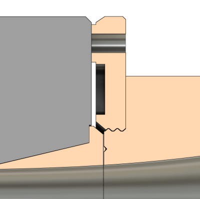
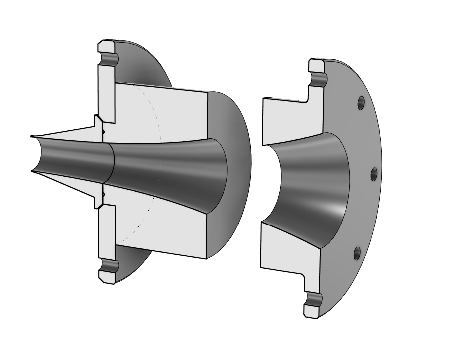
Figure 1 shows the newly developed adapter for the BMS 4554, being cut in the middle where the inner diameter is equal to the original exit diameter of the driver (36 mm). The part to the left of the cut is the effective replacement of the original exit, the part on the right is an optimized continuation for a Gen2 profile. The following text gives a short guide how to actually use the provided adapter kit.

The driver comes with a standard foam gasket and a metal screen underneath. To use the driver with the new adapter, the screen must be removed first. In the provided STL kit there's a simple template just for this. Use a sharp knife to cut through the foam gasket around the template:
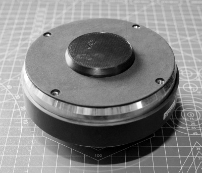
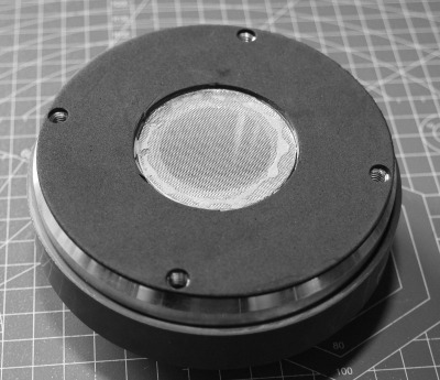
After cutting off the foam (Fig. 3), the screen must be removed. This can be done with small pliers - make a hole in the screen, grip the screen and just peel it off.
IMPORTANT: during all this and the following manipulation with the driver, be sure to hold it oriented so that nothing can fall down into the phase plug. You could have a pretty hard time to get rid of anything once it falls deep into the driver, as the inside of the phase plug is not accessible. You may also take off the diaphragm assembly for the procedure if you want to be absolutely safe.
After removing the screen, remnants of the glue can be cleaned using acetone (Fig. 4, 5). Again, make sure nothing gets into the driver.
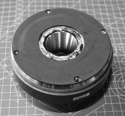
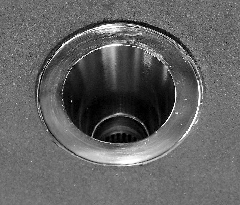
With the driver prepared as in Fig. 5, the next step is to prepare the part of the adapter that will be inserted
into the driver. To achieve the right fit, the end tip of the printed part must be first sanded down. The idea is to have a
more or less sharp edge at the tip, but as this can't be directly printed (at least not with the common FDM printers),
the tip is designed having an additional wall thickness that must be sanded off manually after printing. This is
not a difficult or demanding task, it requires just a piece of sandpaper, but must be done with some care.
Be sure not to overheat the part by sanding, as it could deform easily, depending on the material used.
The provided sanding plug can be helpful for this (Fig. 7).
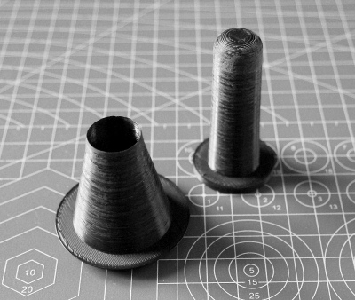
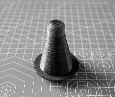
The right amount of sanding should be determined experimentally by continuous trying to insert the part into the driver. You should feel only a very slight push back when inserting the last few millimeters of the part to its place.
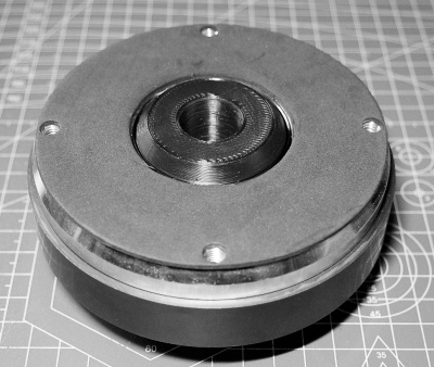
Regarding sanding, it is to be expected that FDM-printed parts in general will require some amount of sanding on the other functional surfaces as well. It is also highly recommended that all the final surfaces are thoroughly sealed - either by paint, lacquer or with an epoxy coating. Unexpected things can happen when the walls are not perfectly airtight, which can easily be the case with printed parts. Even a steep rise of nonlinear distortion was observed.
There are a few things to note here. Typically, the adapter parts will be printed using plastic-based filaments. It is not absolutely necessary to use expensive and more heavy-duty materials (which may be also much harder to print), but then some care must be taken. Plastic parts can't obviously be tightened as strongly as, for instance, metal. The construction has thus been adjusted accordinly.
First, there's an intentional 0.2 mm gap between the new driver exit and the mounting flange:
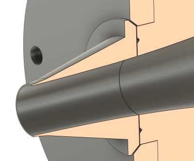
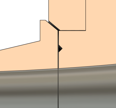
A layer of a soft sealing material should be used to fill this gap to assure a long-lasting airtight connection. An STL file of a gasket is included in the kit (to be printed using a flexible filament), but basically anything that does the job can be used.
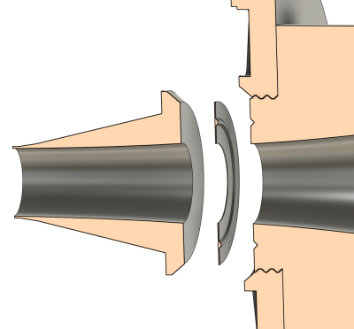
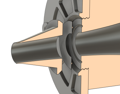
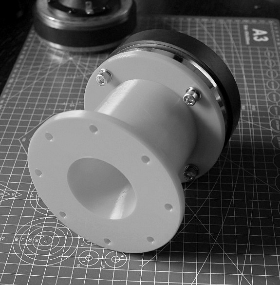
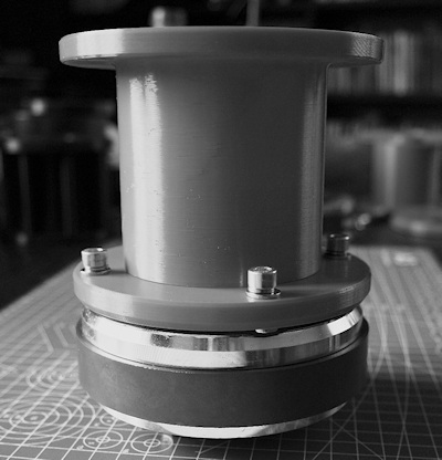
Since the contact area is small, no big force is required to tighten the parts together. The original foam gasket on the driver is pretty stiff and large and just can't be compressed completely by tightening a plastic part. But this is not necessary and the mounting flange has not been designed this way - all that is needed is to place spacer washers around the bolts under the flange, so it's only under the washers where the original gasket gets pressed, and neither that requires a large force. You can use either standard metal washers for M6 bolts (~1.5 mm thick) or you can use the mounting flange with integrated spacers included in the kit (Fig. 11). It is also advisable to print at least a small volume under each bolt head solid (100% infill) through the whole flange thickness. Just be mindful of not overtightening the plastic parts, otherwise they could deform or break.
The adapter can be used with any Gen2 horn, as any other Gen2 adapter.
Have fun!

