The aim of this project was to design a free-standing waveguide with a constant Directivity Index (DI). This is different to e.g. the Gen2 waveguides, where the DI curve intentionally rises gradually with frequency. A constant DI means that the on-axis frequency response matches perfectly the frequency response of the total radiated acoustic power (no matter what the shape of the response is). This alone wouldn't in theory guarantee a flawless performace, but typically, when this goal is actually reached with a horn, it means it must be free of any strong diffraction effects, etc. The R-OSSE profile[1] provides an exceptionally clean listening window as well.


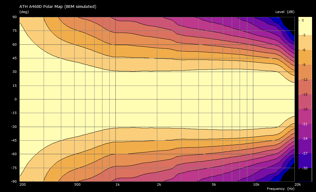
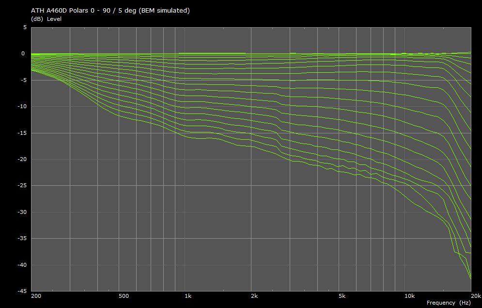
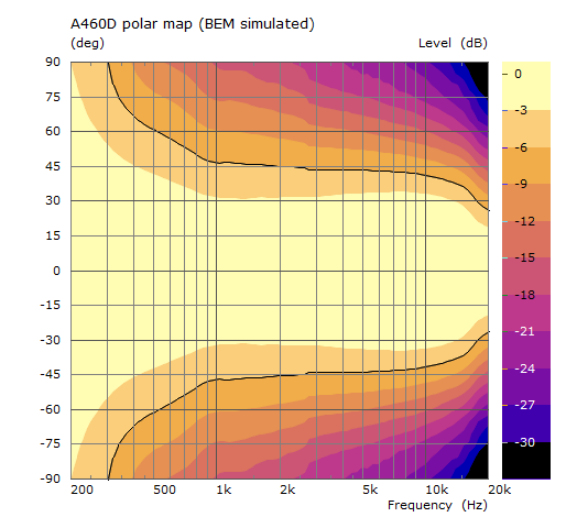
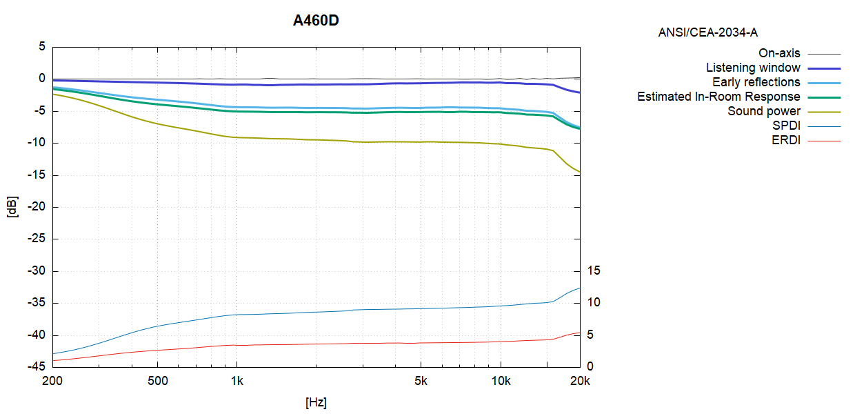
The beamwidth chosen for the design was 90° nominally, which translates to a DI around 9 dB. Figure 1 shows the predicted polar map (black line indicates the actual -6dB countour). Figure 2 shows the performance as defined in the ANSI/CEA-2034 standard[2]. Even though the DI curve is not perfectly constant, and even though it could be done, decision was made to stop at this stage of optimization, where the Early Reflections and Estimated In-Room Response curves are already flat enough. Going further just doesn't seem to bring any additional advantage.
As with any such device, there are two distinctive points on the frequency axis: The point where the mouth is no longer big enough to control the directivity lower in frequency (~1 kHz), and the point where the throat radius is no longer small enough to do the same higher in frequency (~ 15 kHz). Only what's in between is actually controlled by the waveguide (and there's really not much left to be improved).
The kit is available via Cults: https://cults3d.com/:2404194
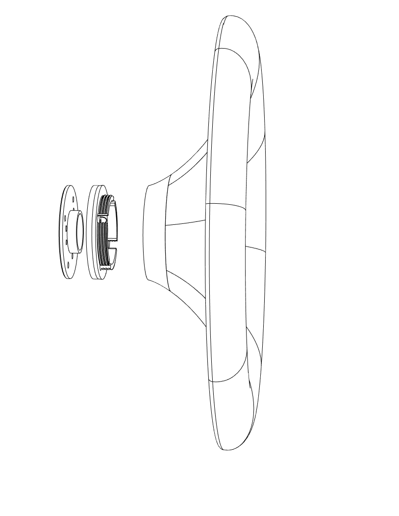
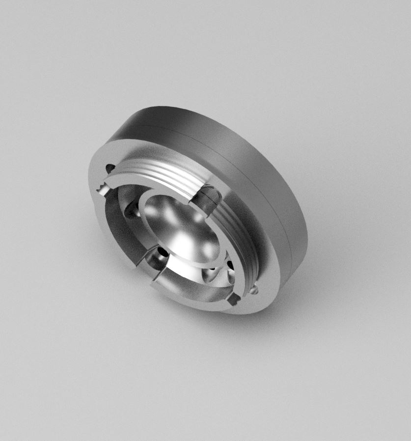
The A460D kit was designed for replaceable throat adapters, allowing mainly different opening angles without the need to redesign the whole device. Figure 3 shows a render of the throat assembly (namely with the 0° adapter).
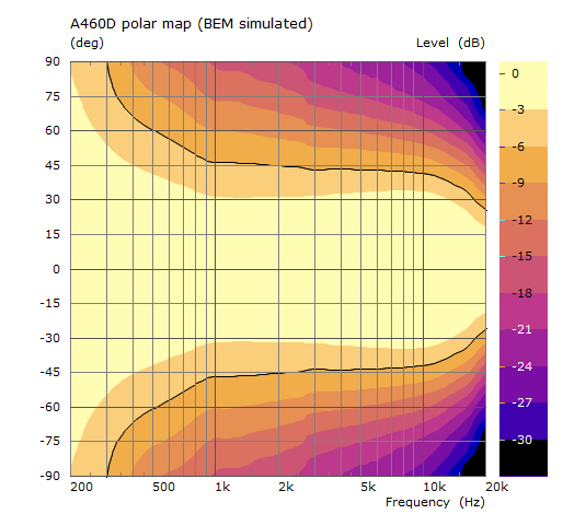
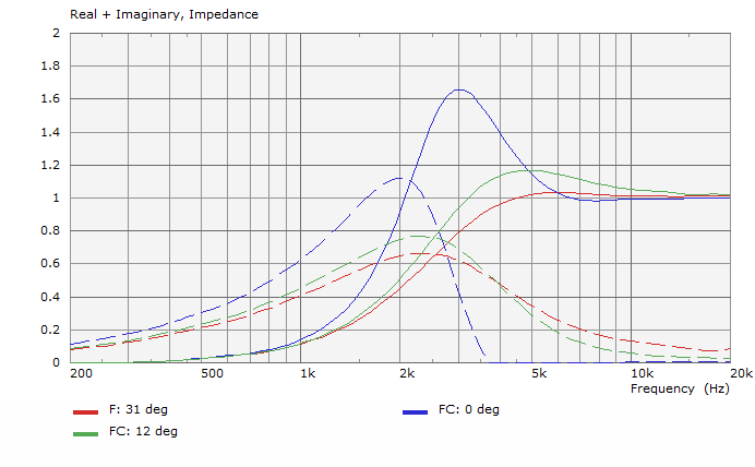
Different throat opening angles affect the directivity above ~12 kHz and also the throat acoustic impedance, both to a degree. The Figure 4 shows polar maps for the throat adapters of 0°, 12° and 31° opening angles.


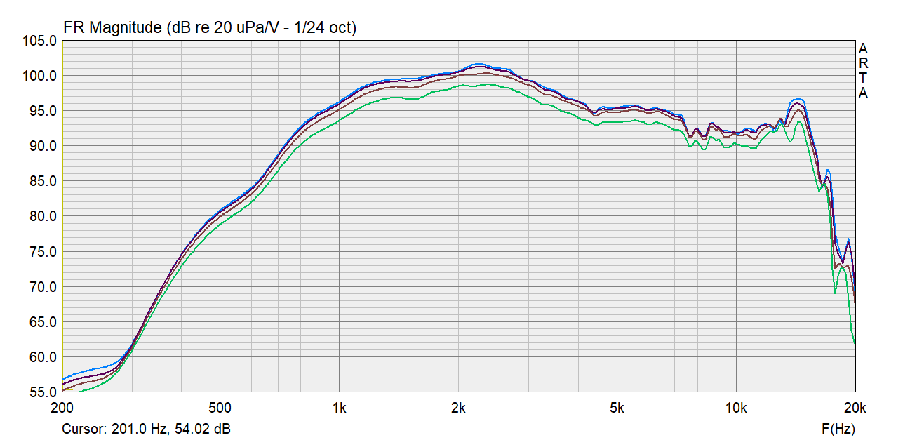
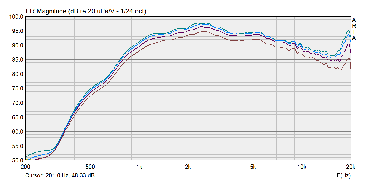
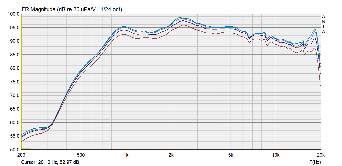
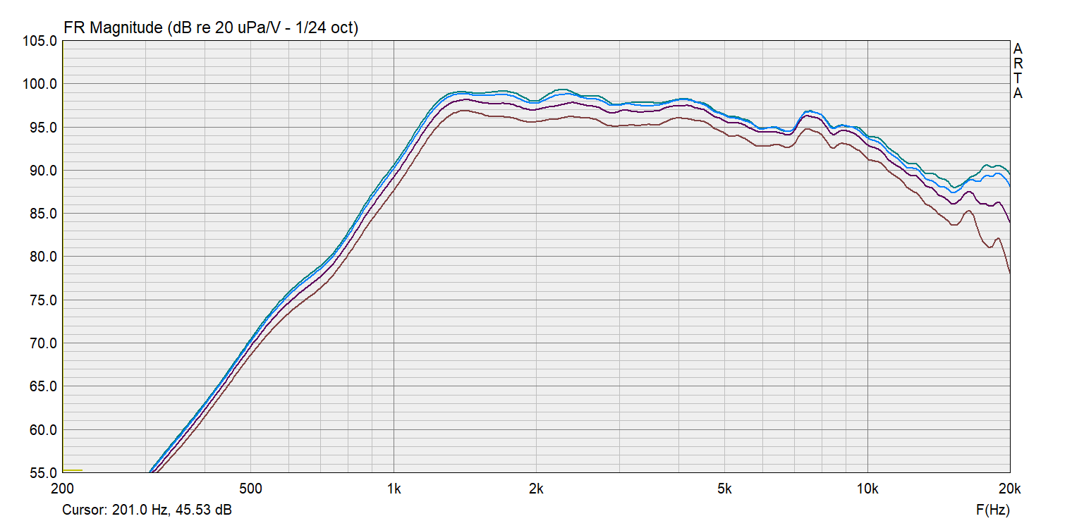
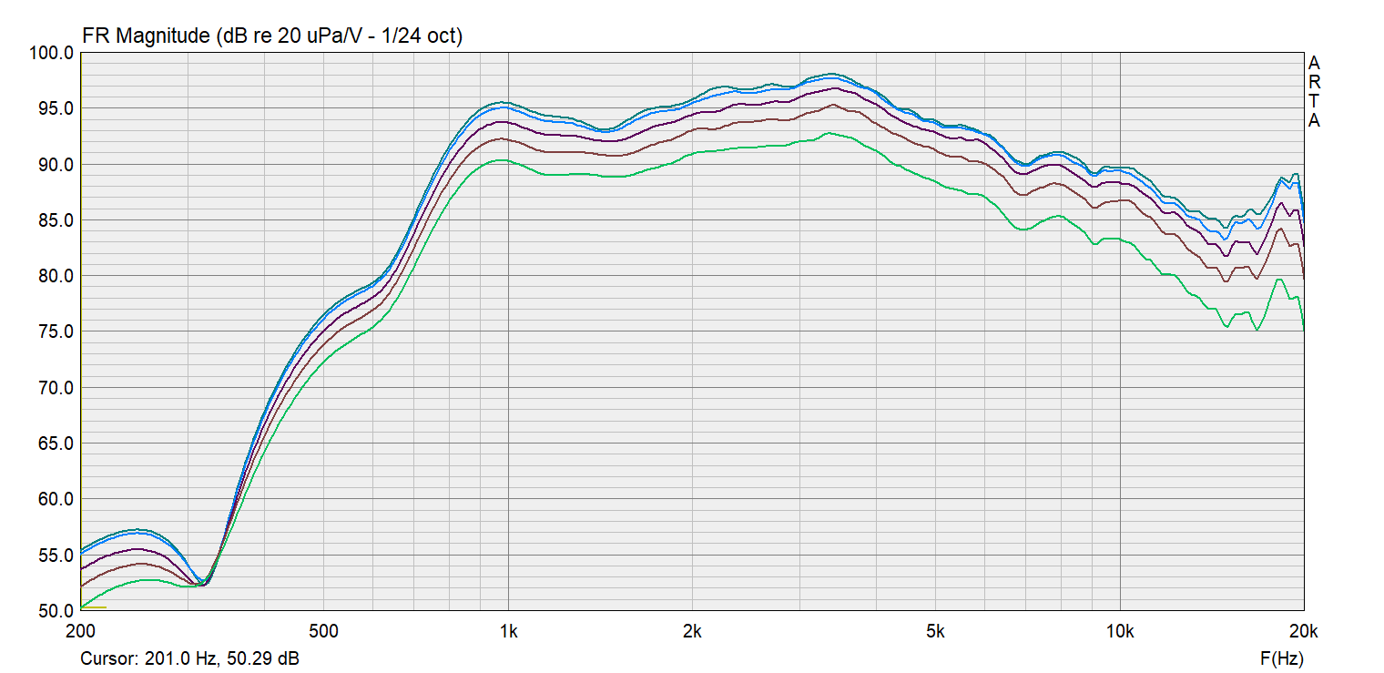
Below are some raw measurements of the A460D prototype that was printed and assembled. (Please see the notes to the Gen2 measurements which also apply here.)
