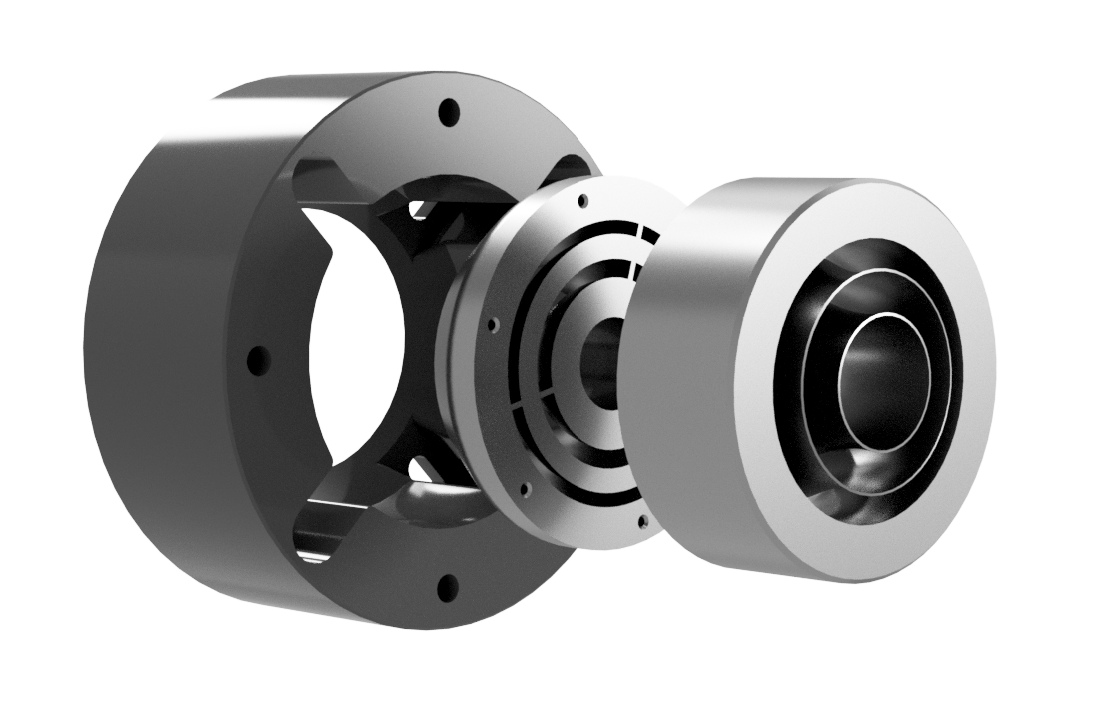
The "Gen2" set of devices offers a unique solution to the DIY audio hobbyists and audiophiles. The main, big and the most demanding parts of the horns need to be made only once, while the throat adapters for different driver sizes, exit angles, extensions and shapes are easily replaceable.
Although being "versatile" in the sense just described, these waveguides offer excellent acoustic performance in any absolute terms, basically free of diffractions and reflections. They represent a carefully crafted balance between controlled directivity, smooth response and acoustic loading by the virtue of the R-OSSE[1] profile used. The frequency responses within the whole listening window are virtually identical - a truly remarkable feature and also an evidence of the absence of any noticeable diffraction effects.
The A520G2 is a kind of "no-compromise", moderately large waveguide, while the A400G2 is basically just a smaller version, still performing extremely well for its size. A460G2 is the latest iteration, maintaining virtually the same overall performace of the large A520G2 down to around 600 Hz, but in a noticeably smaller format (using a slightly different shape of mouth termination). It can be recommended especially for 1" drivers in general, where a bigger device offers typically only a negligible advantage. E520G2 is a segmented version[3] of the A520G2. Performance wise, it is on par with the axisymmetric version, with possible practical advantages. And finally, there's the A620G2, intended for the biggest drivers available, reaching as low frequencies as possible.
The throat adapters marked as 'STD' are the standard, short, non-resonant types. The parts marked as 'EXT' are extended-throat versions, improving on the low-frequency capabilities[2]. Each combination is optimized to provide a smooth, well-controlled directivity with a mildly rising directivity index through the whole operating range. Figure 1 shows a BEM-calculated[5] benchmark of the performance.
Although it stems obviously from its axisymmetric nature, it's still worthwhile to note that the presented data describe the behaviour of the horn everywhere in the far field. This is one of the big advantages of round horns in general - their full performance can be easily assessed using a single polar map, measured or calculated just in one orbit (it's also difficult to cheat, but that would be another topic).
The whole range of adapters can be used with all the Gen2 waveguide bodies. The corresponding ANSI/CEA-2034-A[4] reports for some chosen combinations are shown in Figure 2. For convenience, the data for these reports has been normalized to 5° off axis, meaning that they represent the performace of the device with the frequency response at 5° equalized to being perfectly flat.
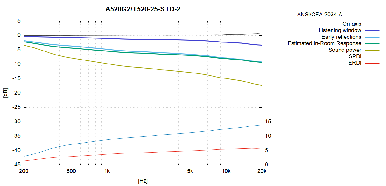
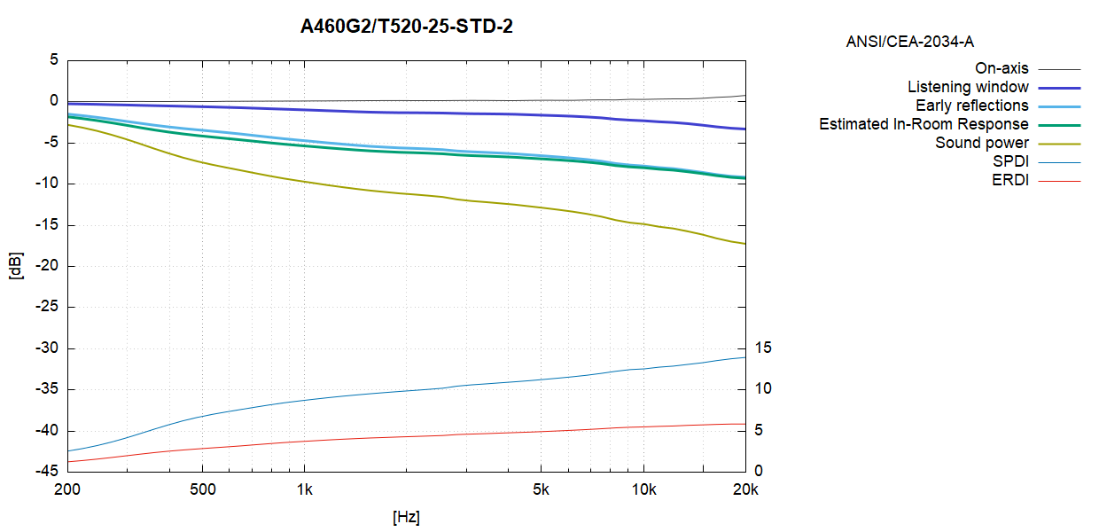
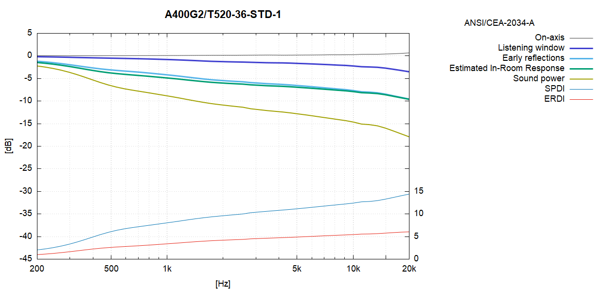
It is to be noted that the directivity (and all the curves in Fig.2) stays virtually the same for all the throat adapters, irrespective of compression driver used or its exit size. There may be small differences above ~15 kHz but overall the performance will be very similar. It is simply because the nominal performance was designed for a 1.4" throat. Smaller-exit drivers will offer the typical advantage of the top octave being cleaner, but without any further advantage in high-frequency directivity. The extended-throat (EXT) adapters still allow even some of the 1" drivers, if not most of them, to be used down to perhaps 600 Hz. The latest addition to this approach is the long adapter for the BMS 4554 compression driver and represents the current culmination of the work.
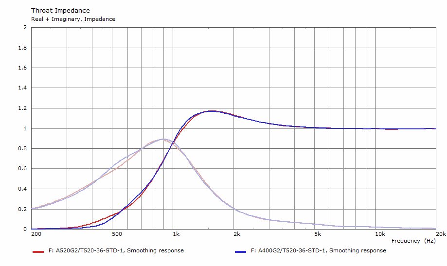
Figure 3 shows normalized throat acoustic impedance for both A520G2 and A400G2, simulated in free air, using the standard 1.4" adapter. Maybe not anticipated by common intuition, the throat impedances are basically the same - they are simply not dependent on mouth size in these kinds of waveguides. In fact, no matter how irrelevant, the low-frequency point(1) of the smaller waveguide is a tiny bit lower in this case.
Acoustic measurements with various drivers are available on the measurements page.
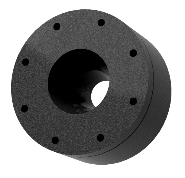
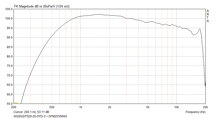
As a "spin off", the A460 horn has been designed, based on the A460G2, but already including a throat section and with the optimization boundaries loosen to not be limited by the existing Gen2 bodies. The result is a waveguide designed and optimized from throat to mouth as a single R-OSSE curve[1]. The opening angle of the 1" throat was set to 21.7°, matching Peerless DFM-2535R00-08, but of course other similar drivers can be used.
 A400G2 ⌀400 x 130 mm (⌀15.75 x 5.12") |
A460G2 / E460G2 ⌀460 x 160 mm (⌀18.11 x 6.30") |
A520G2 ⌀520 x 174 mm (⌀20.47 x 6.85") |
E520G2 ⌀520 x 174 mm (⌀20.47 x 6.85") |
A620G2 ⌀620 x 221 mm (⌀24.4 x 8.7") |
| Part No. / Link |
Input ⌀ |
Low-frequency point (1) |
Input angle (2) |
Length |
Additional info / Driver mounting (3) [mm] |
|---|---|---|---|---|---|
| ⌀25 mm / 1" | |||||
| T520-25-STD-1 | 25.4 mm | 670 Hz | 12° | 61 mm | 4xM6/⌀76 + 3xM6/⌀57 |
| T520-25-STD-2 | 25.4 mm | 740 Hz | 31° | 46 mm | 4xM6/⌀76 + 3xM6/⌀57 |
| T520-25-STD-3 | 25.4 mm | 720 Hz | 22° | 52 mm | 4xM6/⌀76 + 3xM6/⌀57 |
| T520-25-EXT-1 | 25.4 mm | 440 Hz | 3.2° | 135 mm | 4xM6/⌀76 + 3xM6/⌀57 |
| T520-25-EXT-2 | 25.4 mm | 550 Hz | 7.2° | 90 mm | 4xM6/⌀76 + 3xM6/⌀57 + 2xM5/⌀57 |
| ⌀36 mm / 1.4" | |||||
| T520-36-STD-1 | 36 mm | 580 Hz | 8.8° | 41 mm | 4xM6/⌀102 |
| ⌀40 mm / 1.5" | |||||
| T520-40-STD-1 | 40 mm | 530 Hz | 0° | 46.5 mm | 4xM6/⌀102 |
| ⌀50 mm / 2" | |||||
| T520-50-STD-1 | 50 mm | 500 Hz | 12.5° | 10 mm | 4xM6/⌀102 |
| Special Adapters / Driver-Optimized | |||||
| T520-ROSSO-STD | 26.9 mm | 645 Hz | -- | 46 mm | SB ROSSO-65CDN-T 4xM6/⌀102 |
| T520-DF10-171K | 25.0 mm | 680 Hz | -- | 60 mm | Lavoce DF10.171K 4xM6/⌀76 |
| T520-JBL2450 | 38.1 mm | 530 Hz | -- | 40.7 mm | JBL 2450 4x6.6mm/⌀82.5 |
| T520-ND3N | 36 mm | 540 Hz | -- | 47 mm | 18Sound ND3N 4xM6/⌀102 |
| T520-4554-EXT | -- | 520 Hz | -- | 140 mm | BMS 4554 (new 12/2024) 4xM6/⌀102 |
| T520-4552-EXT | -- | 520 Hz | -- | 140 mm | BMS 4552ND (12/2024) 2xM6/⌀76.2 |
| T520-5530ND-EXT | -- | 520 Hz | -- | 140 mm | BMS 5530ND (01/2025) 3xM5/⌀57 |
| T520-1720 | -- | 590 Hz | -- | 84 mm | Celestion CDX1-1720 (03/2025) 4xM6/⌀76 |
| T520-760 | -- | 470 Hz | -- | 90 mm | Radian 760NeoPB (02/2025) 4xM6/⌀102 |
| External Shaping Plugs (experimental)(4) | |||||
| T520-ESP-50 (set) | -- | 420 - 550 Hz | -- | 50 mm | |