As anyone who ever tried to design an acoustic device called horn or waveguide will confess, to get a constant directivity together with a high acoustic impedance in a wide frequency range is a difficult task. One can easily get either a good, well-controlled directivity, or a high acoustic resistance at the throat (i.e. efficiency), but not so easily both at the same time. Various strategies were developed over time that try to deal with this situation, typically sacrificing the radiation pattern at least in one direction, most commonly the vertical one, inevitably affecting also the overall power response. Numerous kinds of so-called diffraction slots are also used for this task, not without their own problems. Multicell horns are another example. Not so rarely, this causes more problems than it solves.
To obtain a high acoustic resistance at the throat, one needs a slowly expanding horn. On the other hand, to get a well-controlled or constant directivity, one needs to transform the input wavefront to spherical as soon as possible and continue with a more or less conical shape (if it is not possible to have a spherical wave to start with, as it's typically not). Slowly expanding horns, such as exponential, lead to strong beaming with increasing frequency, whereas the constant directivity (conical) horns have typically somewhat limited low frequency capabilities. Of course, one can always move somewhere in between, closer to either of both extremes - that is where the R-OSSE and OSSE profile formulas are especially useful, as they both easily allow to create shapes freely within this whole range, still with a smooth termination, paramount to a top-notch performance in all cases.
One of the early attempts to solve this, as a part of the ATH project, was a wave-forming device (called External Shaping Plug, Fig.1, see [2]), that would take a flat input wavefront and transform it into spherical via a set of slowly expanding discrete channels. While the numeric simulations predicted virtually perfect results for ideally flat input wavefronts, even for 2" throats, real-life imperfections of the actual wavefronts produced by compression drivers left a lot to be desired. Obviously, a different approach was required.
During a testing of a 1.4" throat waveguide, an idea came to mind to try to connect a 1" driver to that waveguide via a simple conical adapter. The adapter was simply made to match the input angle of the waveguide, so its length, connecting the 1" exit to the 1.4" throat aperture, had to be roughly 100 mm (see Fig.2). The waveguide used was ATHEX 460-36 (6° input angle) and the driver was Peerless DFM-2535R00-08.
Based on numerous previous simulations it was anticipated that such an added piece of duct would cause a substantial resonance, as there will be a reflection at the duct/waveguide interface, presumably due to wavefront mismatch (see [1], page 21). Such reflection is always present, and the longer the duct (or an exit section of a compression driver), the stronger it should be.
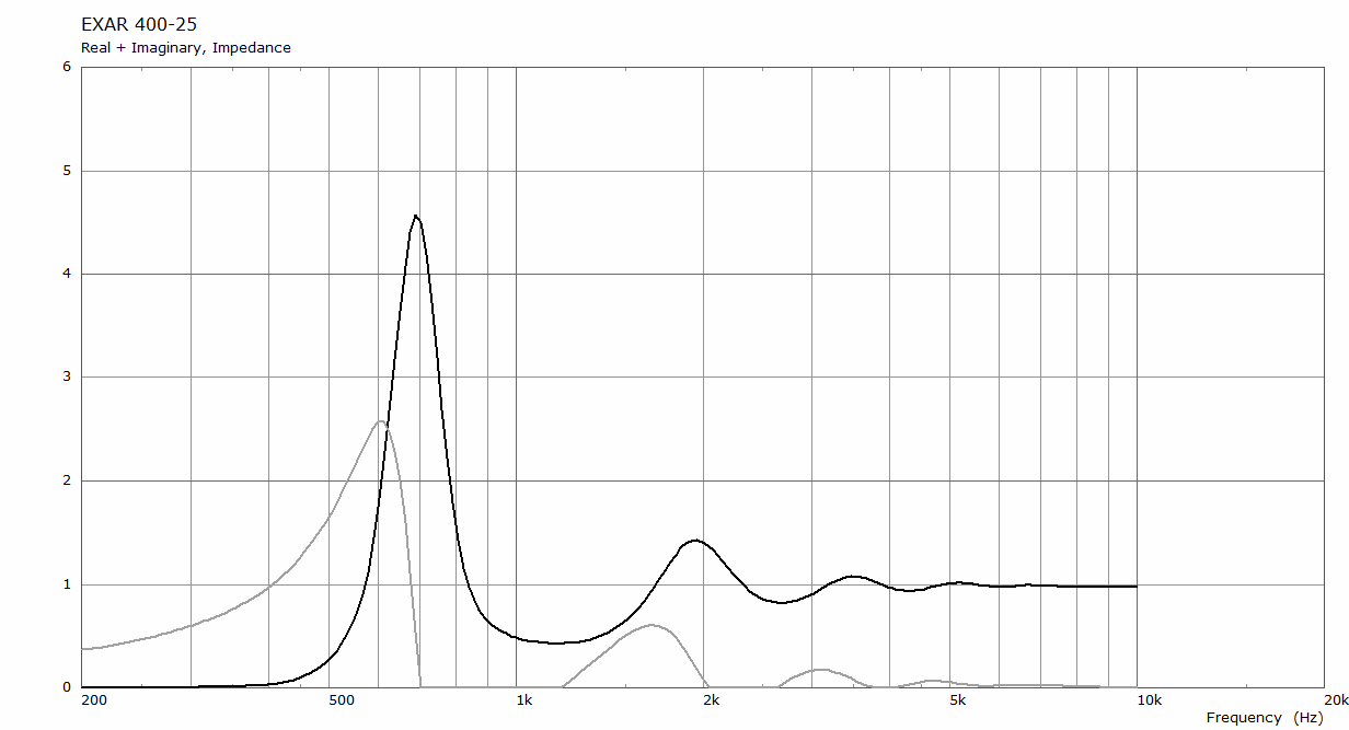
Fig.3 shows a typical throat impedance for an extended horn, as calculated for a BEM model using ABEC3 [3]. It is to be noted that around 700 Hz the acoustic resistance is roughly an order of magnitude higher than without the extension (not shown).
What was not anticipated at all, however, is the actual measured frequency response:
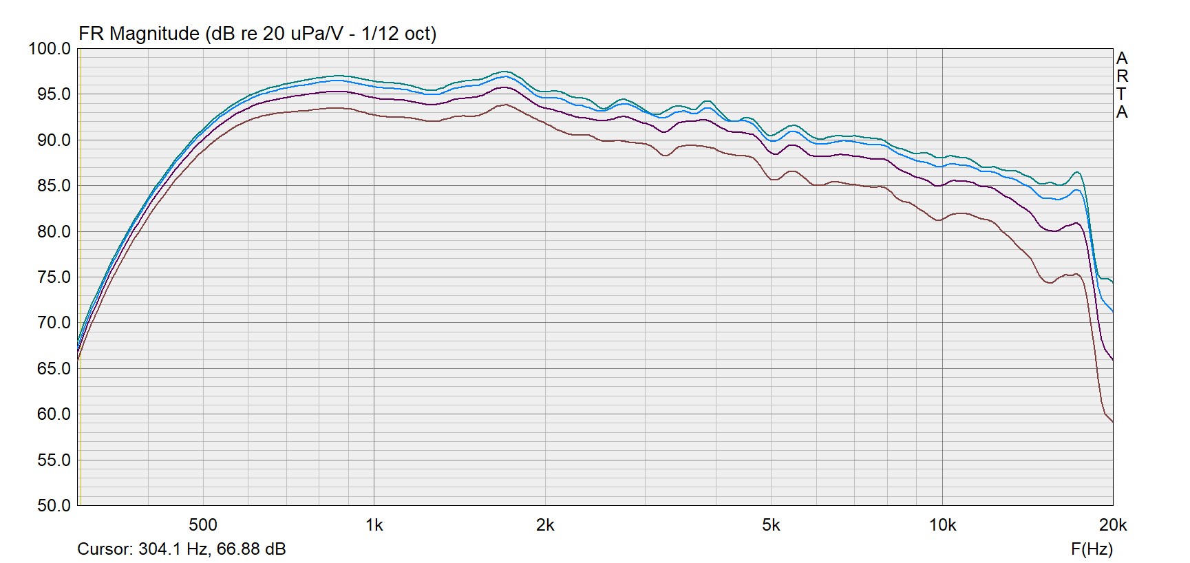
This is a raw response, without any EQ, and there is no hint of any strong peaks, originally expected. What happens instead is a substantial gain in low frequency efficiency - this is certainly not what is commonly observed for a 35mm diaphragm driver in a constant directivity horn. What the simulations did predict accurately, however, is that there's no effect on directivity. And indeed, there's none - it is still the same radiation pattern of the same 1.4" throat as without the extension.
The above picture shows the frequency responses of the very first (quick & dirty) try, with the waveguide/duct/driver interfaces not perfectly aligned. Another attempt was made, this time with a bit more care involved:
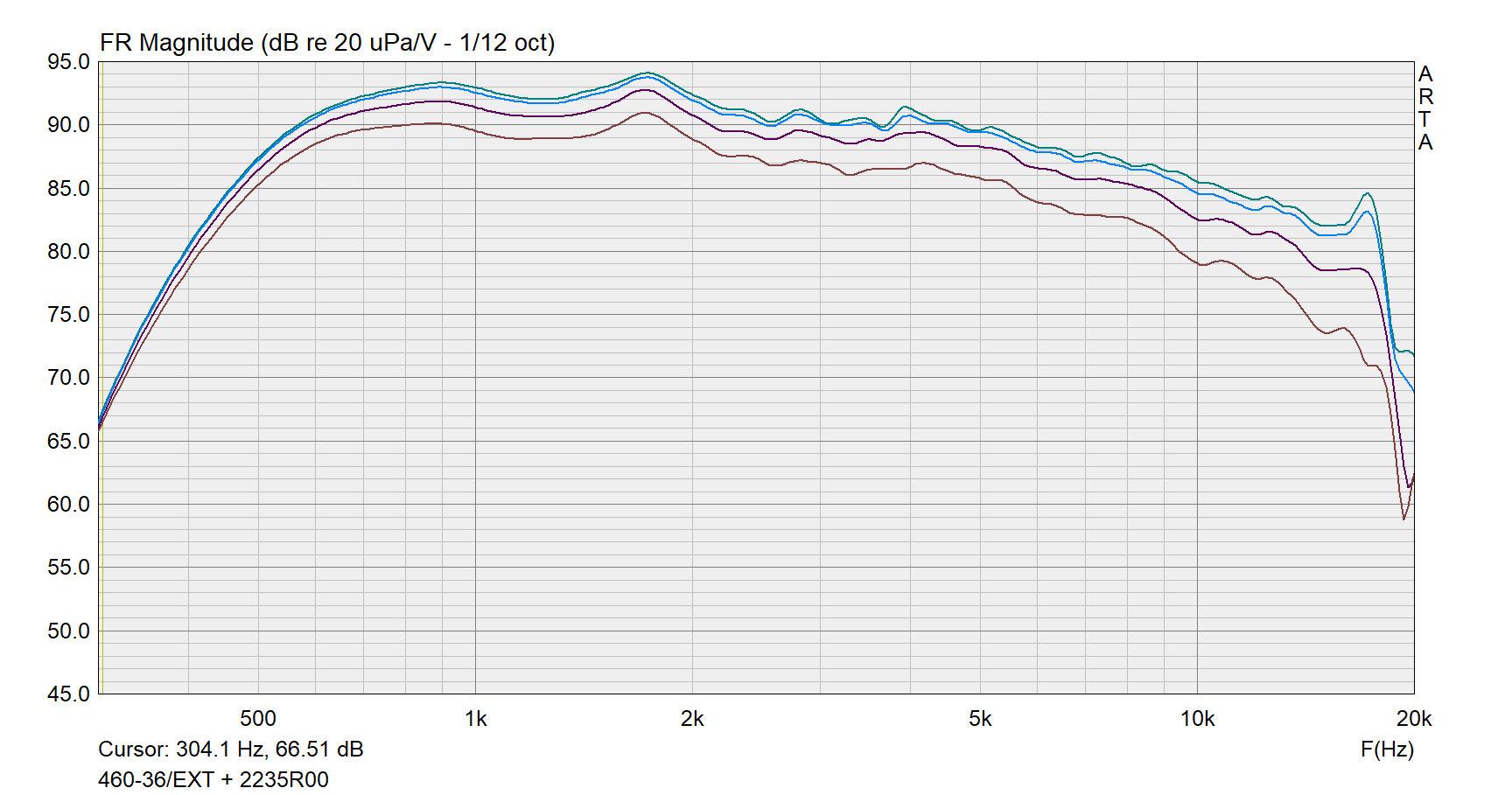
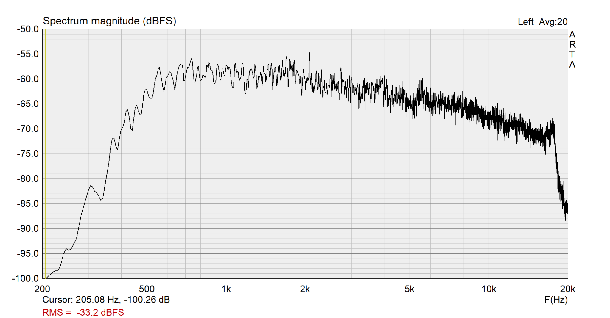
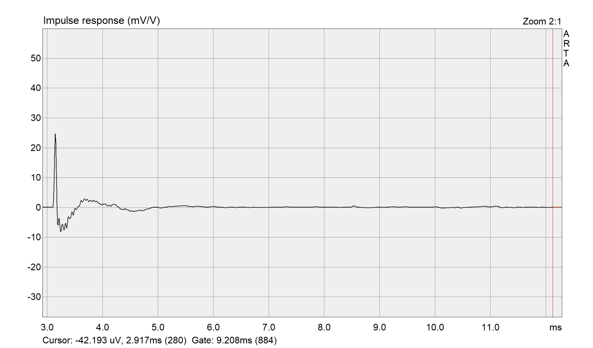
With gated measurements, as in the previous pictures (~5 ms), there's always the risk of not capturing possible high-Q features of the frequency response - as the applied time window truncates the impulse response, it effectively limits the frequency resolution available. To further check that there are no hidden resonances, more measurements were taken, this time with a longer (or no) time window, accepting the fact that reflections appear in the measured data:

Obviously, to simulate this kind of device accurately, a detailed model of the compression driver used would have to be available. No such attempts were made so far and there is still a lot yet to be understood. It is assumed that the length of the extension, perhaps together with its expansion rate is what determines the results for a particular driver and waveguide used. How exactly does the extension interact with a driver is not very clear at this point, at least not to the author of this text.
So far no experiments were done using cylindrical (or even narrowing conical) extension ducts. It is foreseeable it will work as well, without the downside of increasing the effective horn throat diameter.
For best results it seems advantageous to start with as small entry aperture as possible. The ending diameter of the extension is still what determines the high-frequency directivity, as in a case without the extension. With the standard 1" exit drivers it is easily possible to reach the directivity of a 1.4" throat, or similar. If we consider this to be good enough (which it probably is), we are done. But technically, there's also a better way.
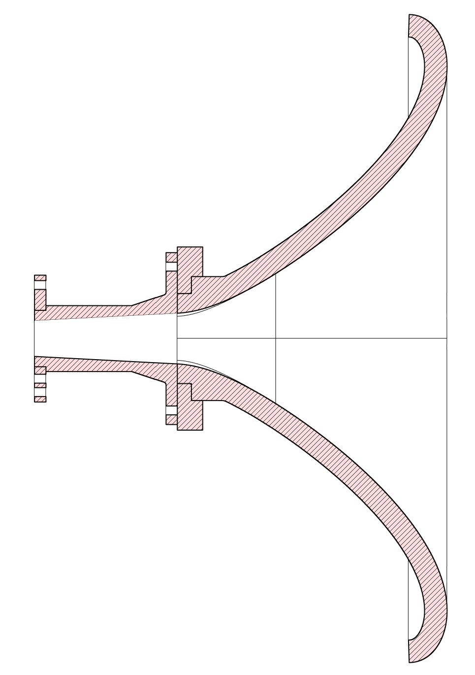
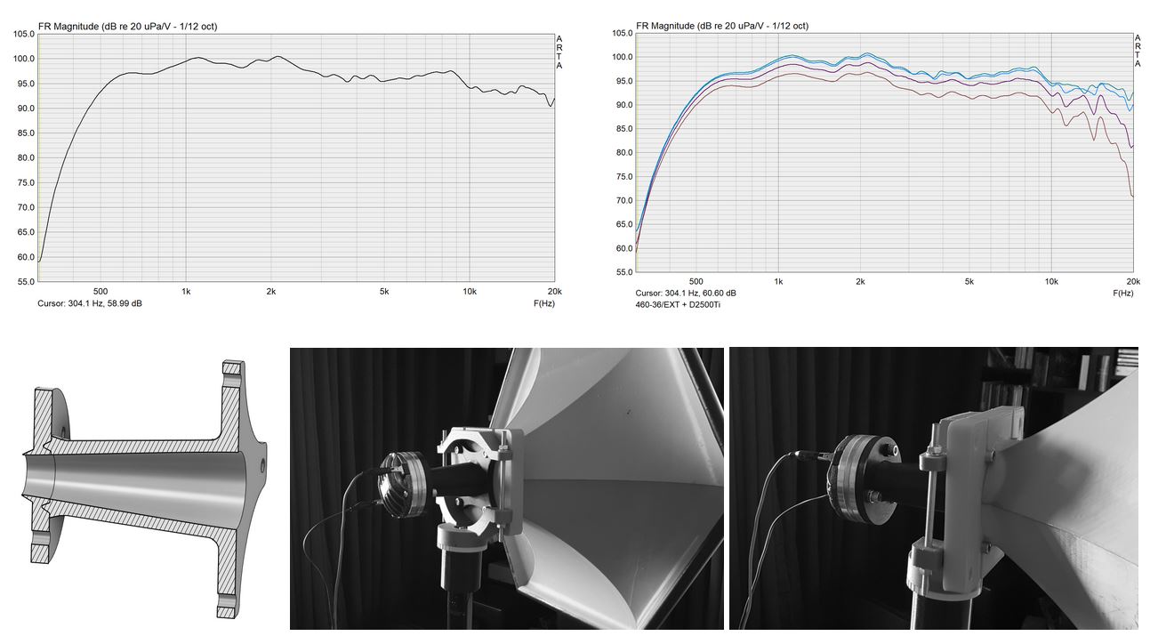
Often, phase plug of a compression driver doesn't terminate at the driver's very exit, but a segment of a conical duct is present between the phase plug and the exit aperture of the driver. The angle of this duct is commonly recognized as the "exit angle" of a compression driver. Now if we are going to insert an extension duct between the driver and the horn, it makes a lot of sense to start the extension right at the exit of the phase plug inside the driver, not at the driver's exit. This seems especially useful in a case of a suitable 1.4" exit driver, so that the extension could start at a (generaly) smaller diameter of the phase plug exit and still connect to the horn via a ~1.4" aperture.
The following image shows a 1" driver (Selenium D2500Ti-Nd), used with a throat plug and an extension similar to the experiments above.
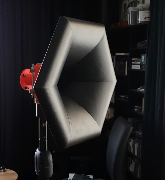
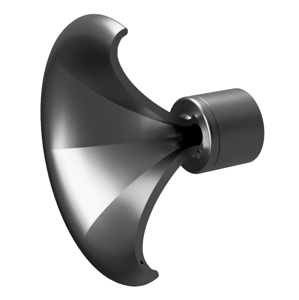
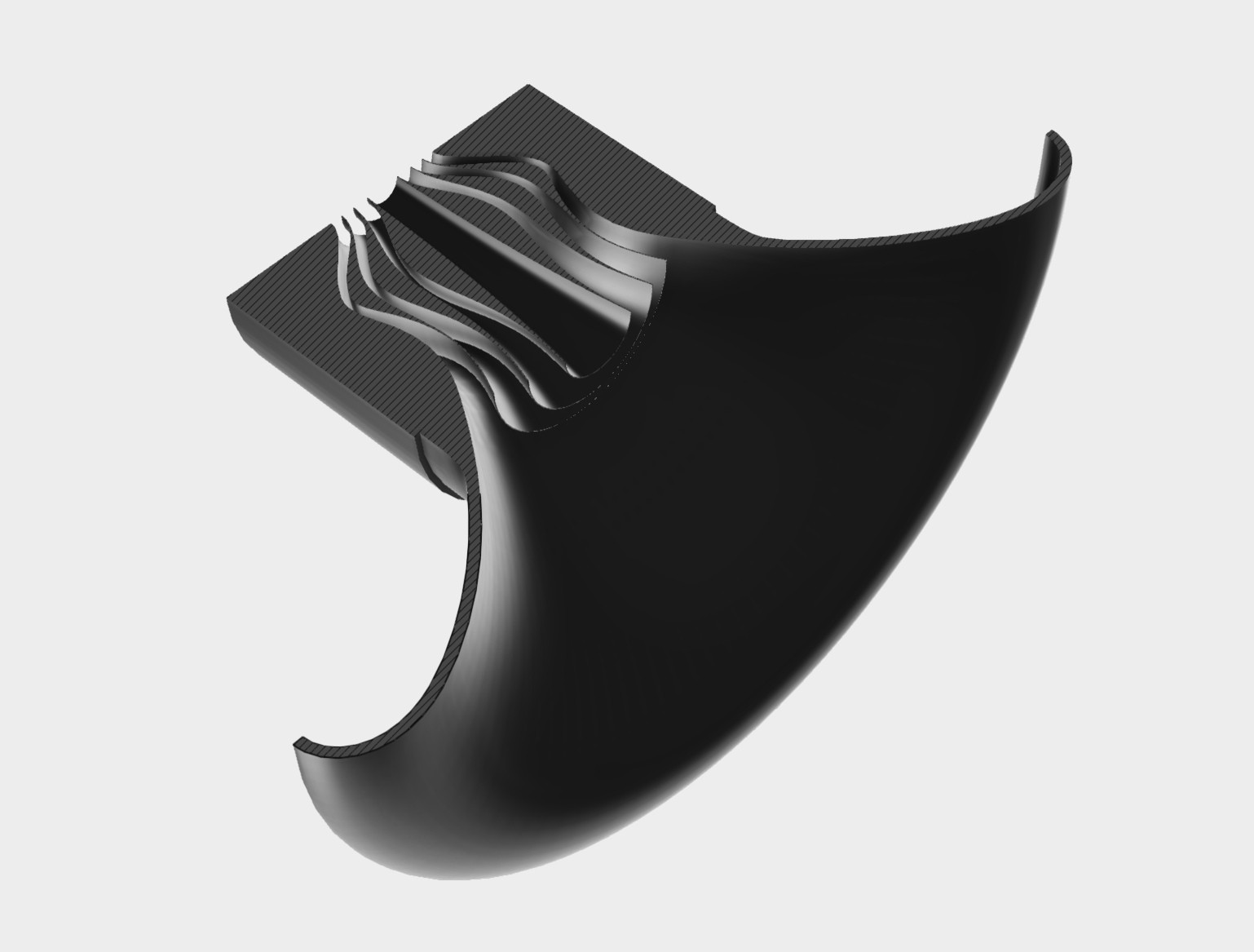
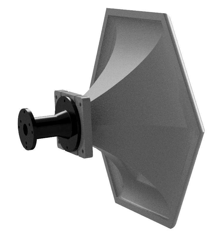
All the experiments described above were carried out using an ATHEX waveguide (Fig.10). It performs very well but the appearance may be a bit too extravagant for some. The idea behind the EXAR waveguides was to combine all the described features in a visually more conventional package. With 3D printing in mind, the aim was to keep the basic segmented shape, as it makes it all a bit easier. The result is a shape that smoothly transforms from circular throat, through a hexagonal middle part to circular mouth (Fig.11). It is still kind of reminiscent of the horn shapes of the past, with -as we believe- the most advanced features of today.