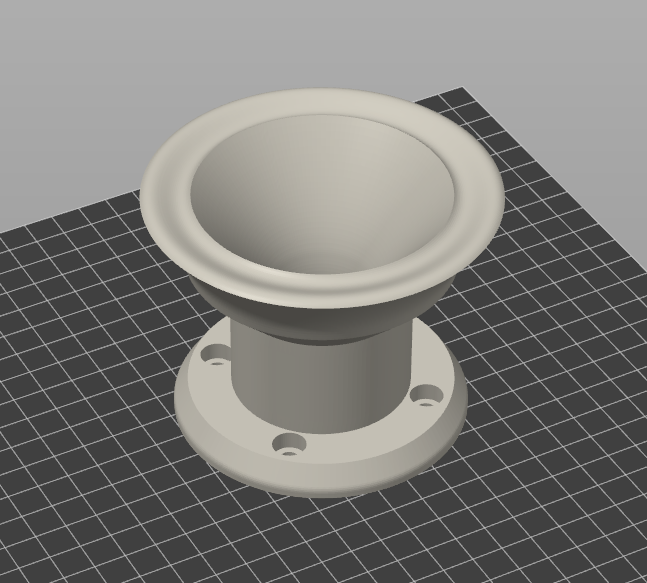
ATH280EX-MK2
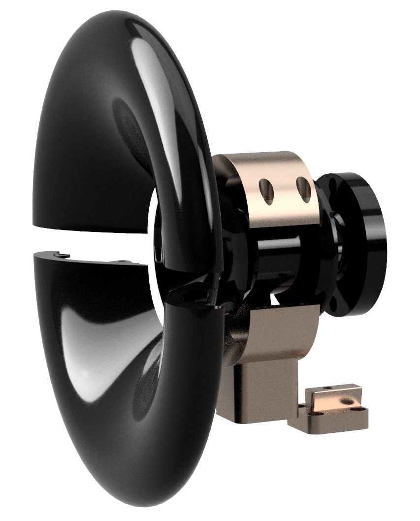
⌀280 x 144 mm / 1" Extended-Throat Waveguide
⌀280 x 144 mm / 1" Extended-Throat Waveguide
The MK2 is an improved version of the ATH280EX waveguide kit. Emphasis was put on the following aspects:

The opening angle of the 1" throat is zero, basically making a segment of a tubular duct. This is to be able to extend the length of this segment as best-suited for a particular driver used. The transition between this straight-tube segment and the R-OSSE [1] part is achieved with a Bézier curve. More about throat extensions can be found in the Technical Note for EXAR waveguides.
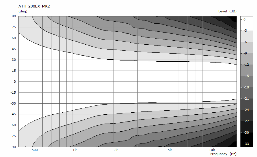
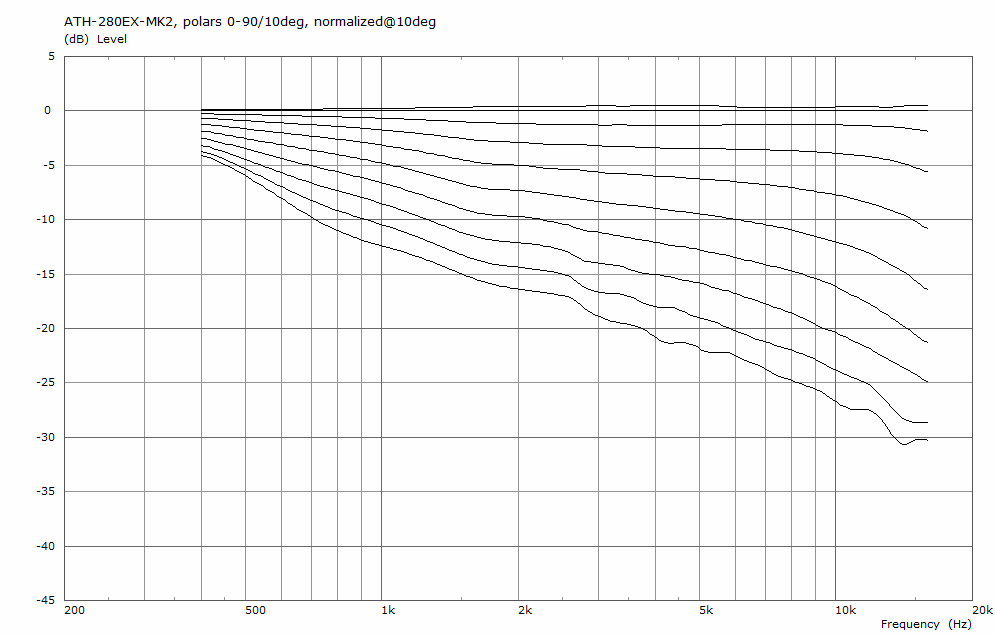
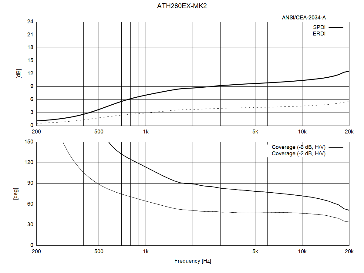
Fig.2 shows the directivity index and coverage angles of the device (all BEM-simulated).
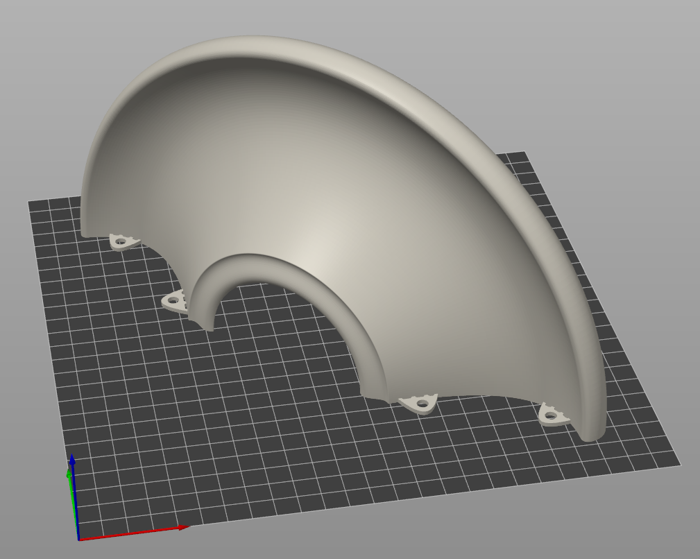
The waveguide is available as an STL kit, including a DXF drawing of the contour. The parts are designed with only a minimal need of print supports, equppied with self-centering rings, overall making the assembly as simple as possible.
As always with the 3D printing, it's not really possible to provide a detailed procedure or print settings, as it's so dependent on a particular equipment and materials used, etc. Everyone will simply know the capabilities of their 3D printer(s) best. Anyway, Fig.3 and Fig.4 show the intended placement of parts on a print bed (print bed at least 205 x 205 mm with print height of 140 mm is required).
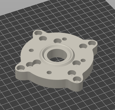
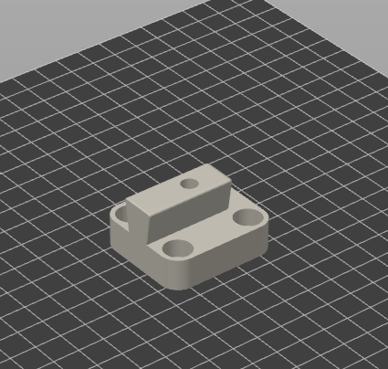
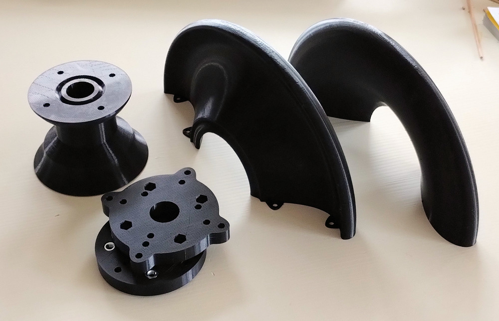
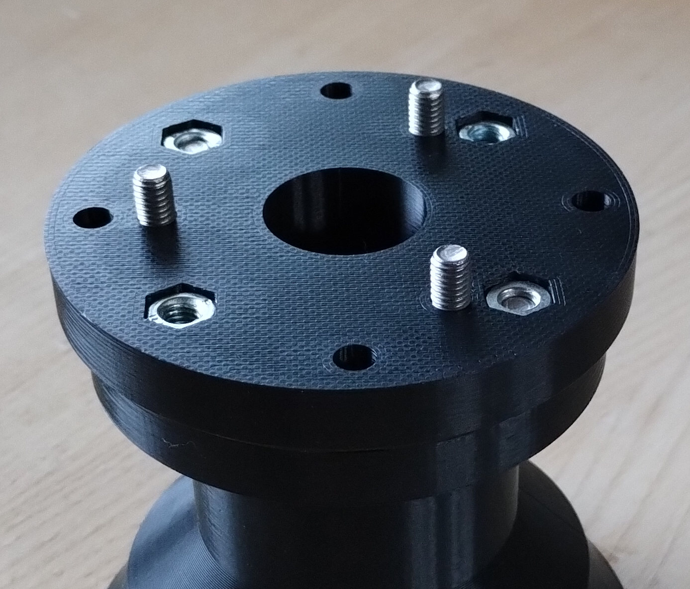
Note that there are two different CD (compression driver) mounting flanges in the kit: The FLANGE-57-76 for bolts at 3x57 and 4x76 mm pitch (Fig.5/right), and the FLANGE-57-76-102 also for the pitch 4x102 mm (Fig.5/left).
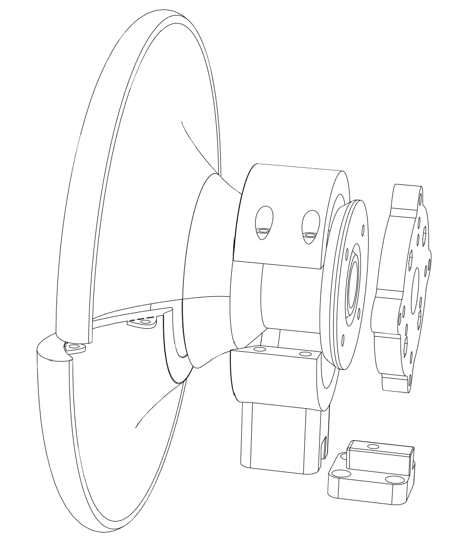
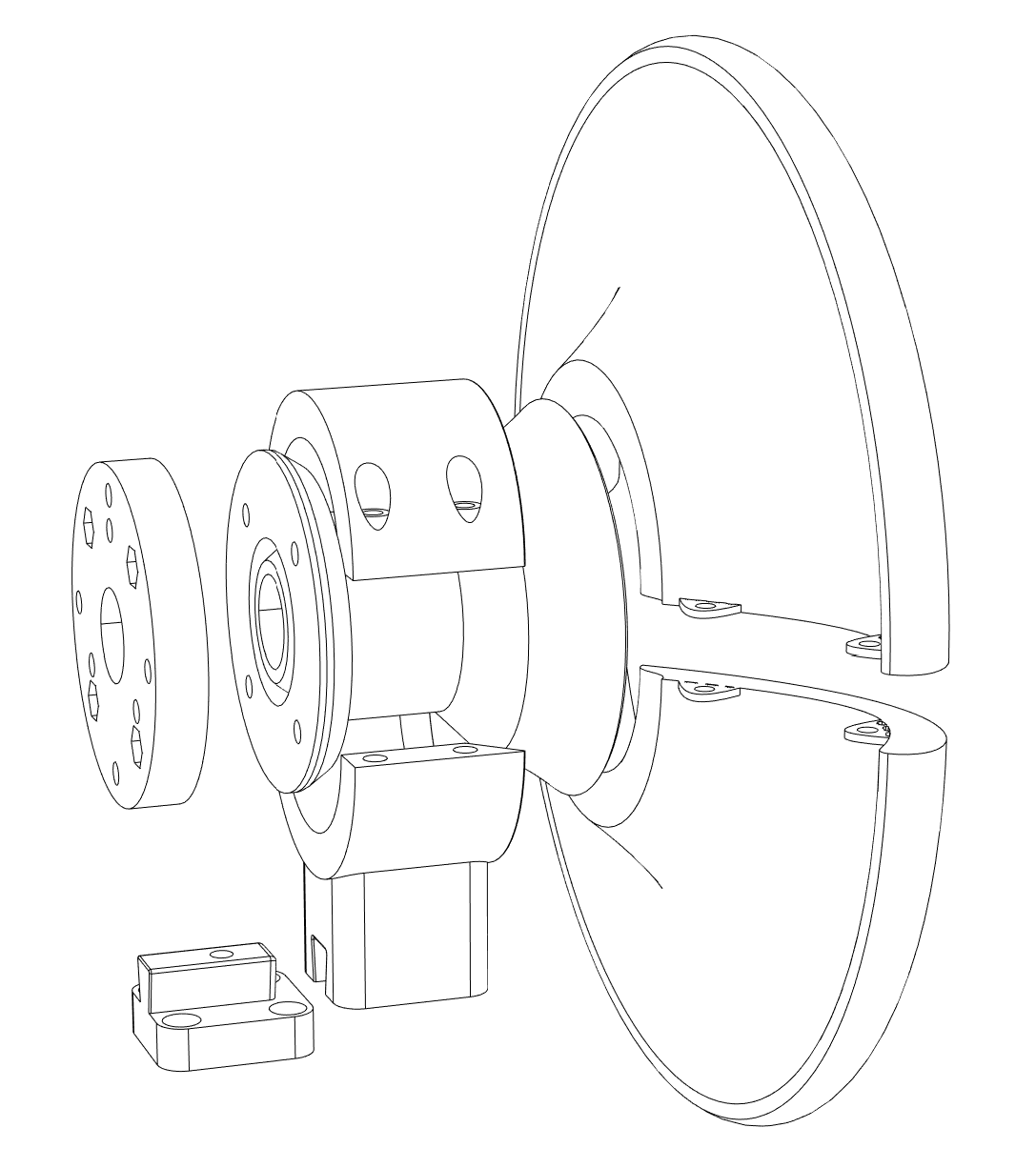
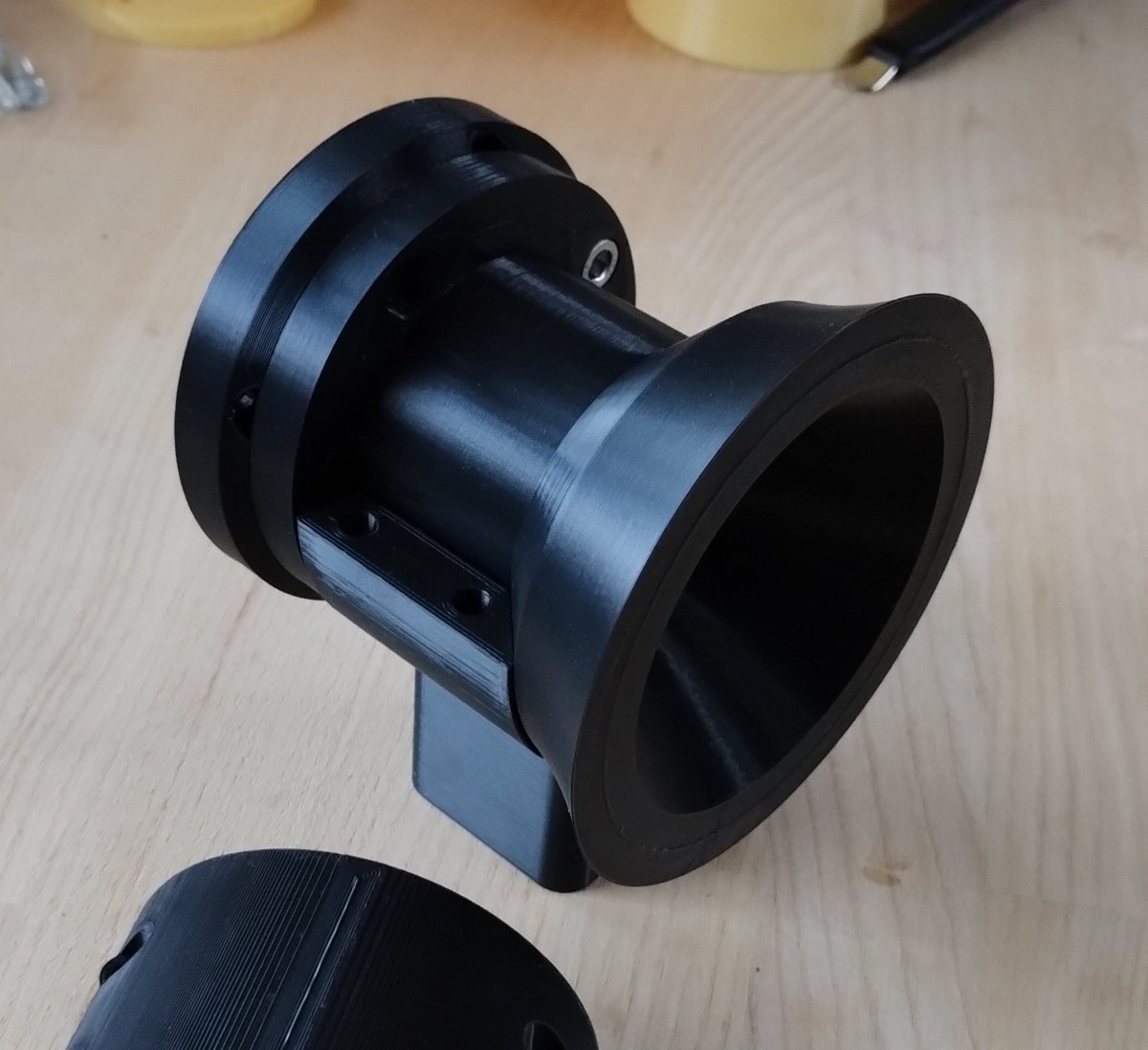
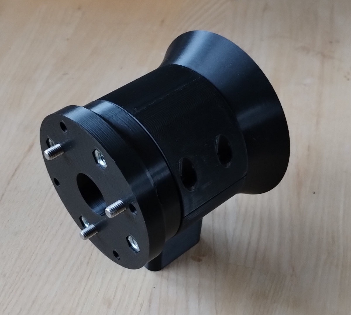
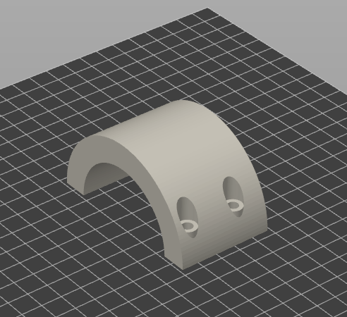
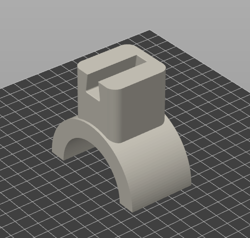
There's an intentional small gap between the waveguide body and the holder. This is meant to be filled with a layer of some damping material, either a piece of foam, rubber or something similar.
M5 thread inserts (e.g. ruthex) fixed (heat-sealed if possible) in the bottom holder part are needed for clamping the two parts of the holder together. To clamp the mounting flange to the waveguide body, ordinary M6 nuts are used.
Fig.6 shows the printed base with a mounting flange, together with an (unfinished) holder.